Installation Instructions
Gate Valves Product Range

Last Updated

December 4, 2020

Flowflex reserve the right to alter the product ranges and specifications associated with its products without prior notice

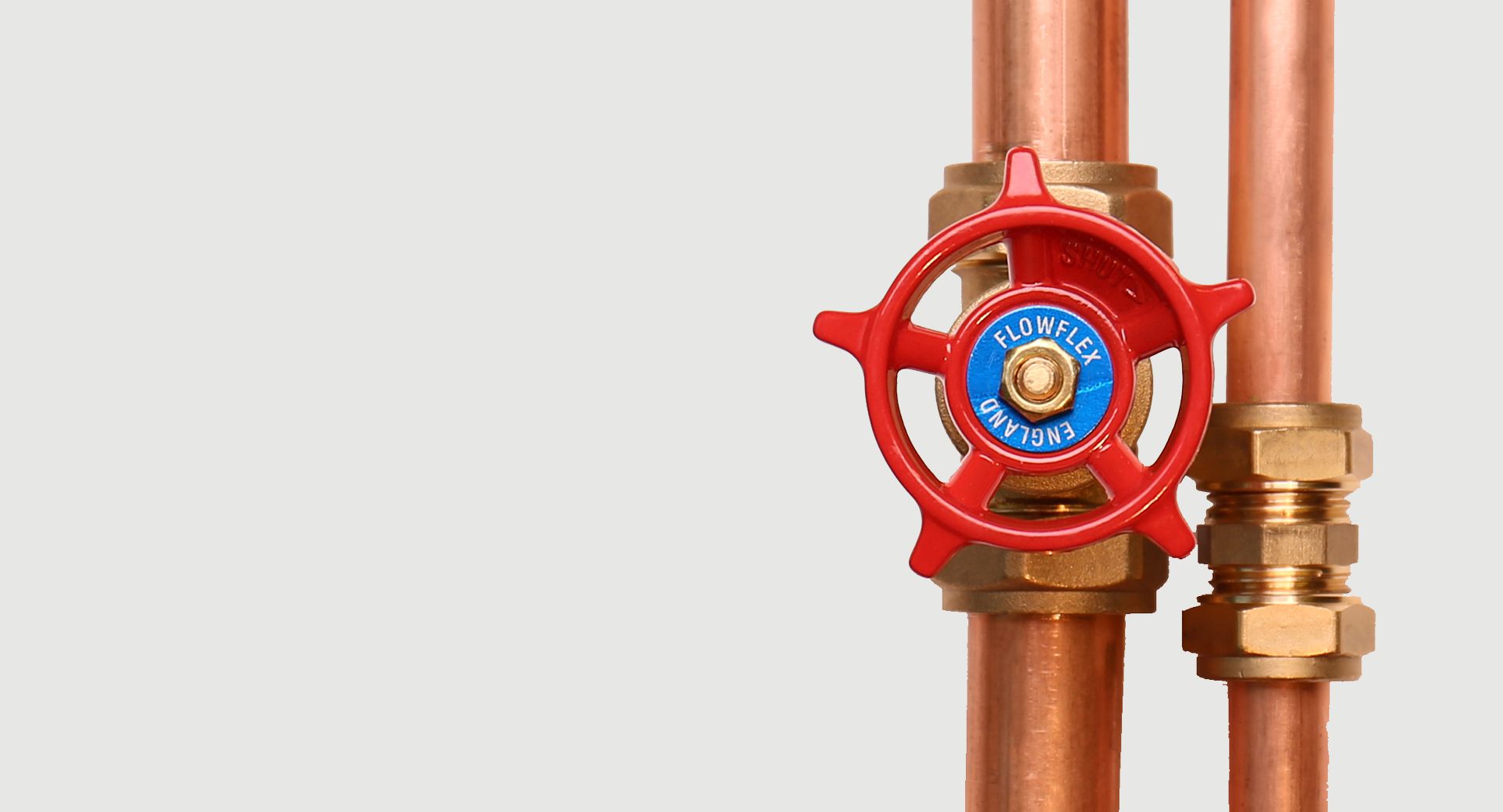
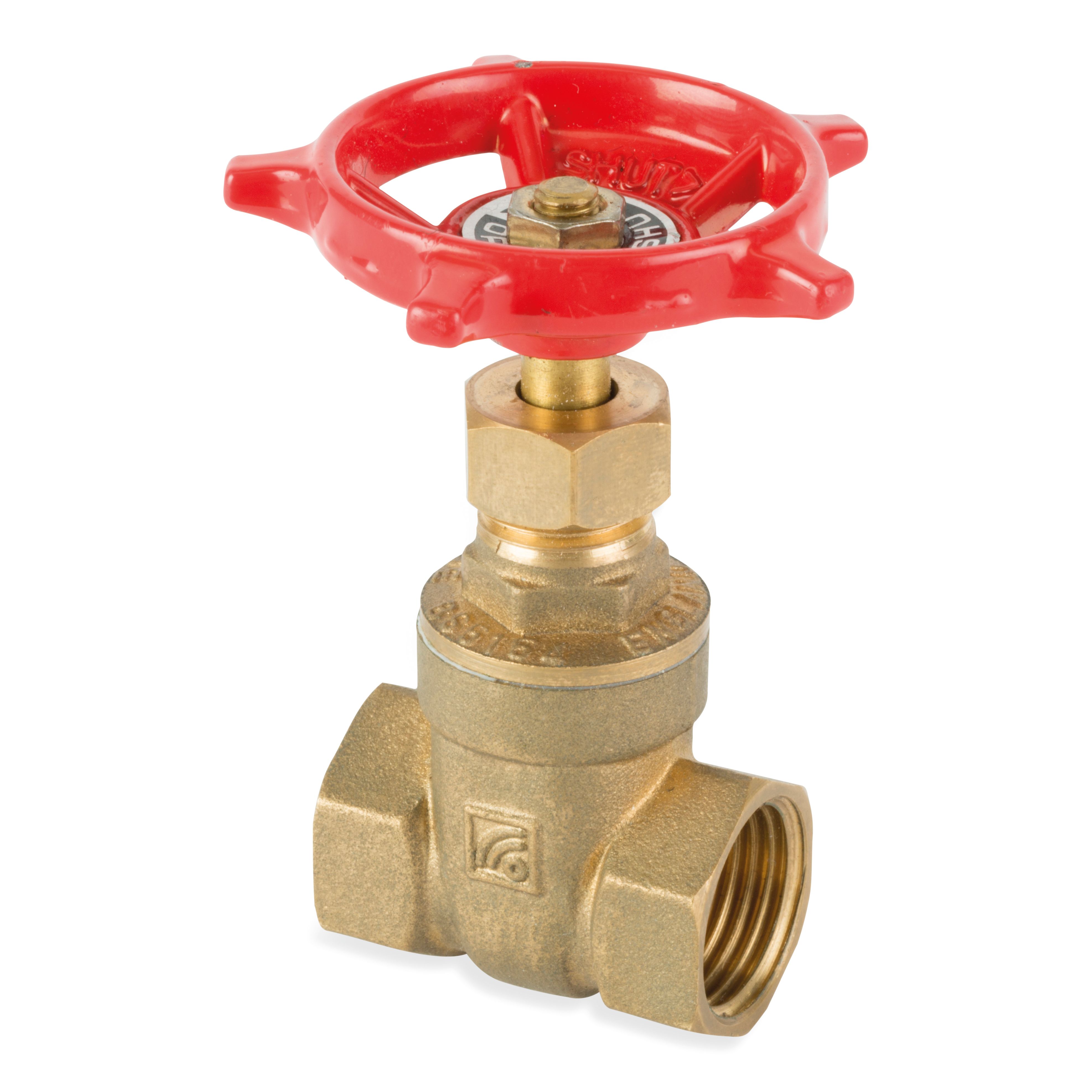
Flowflex Gate valves are installed in systems to isolate flow, and should not be used as control or regulating valves. By turning the stem, the gate inside the valve moves up and down to either interrupt or facilitate the flow of the system.

Gate valves are typically chosen where minimum pressure loss is required, as when fully open, there is very little to interrupt flow. Furthermore, and advantage of using a Gate Valve is that its slow process of closing mitigates the effects of water hammer in your system.

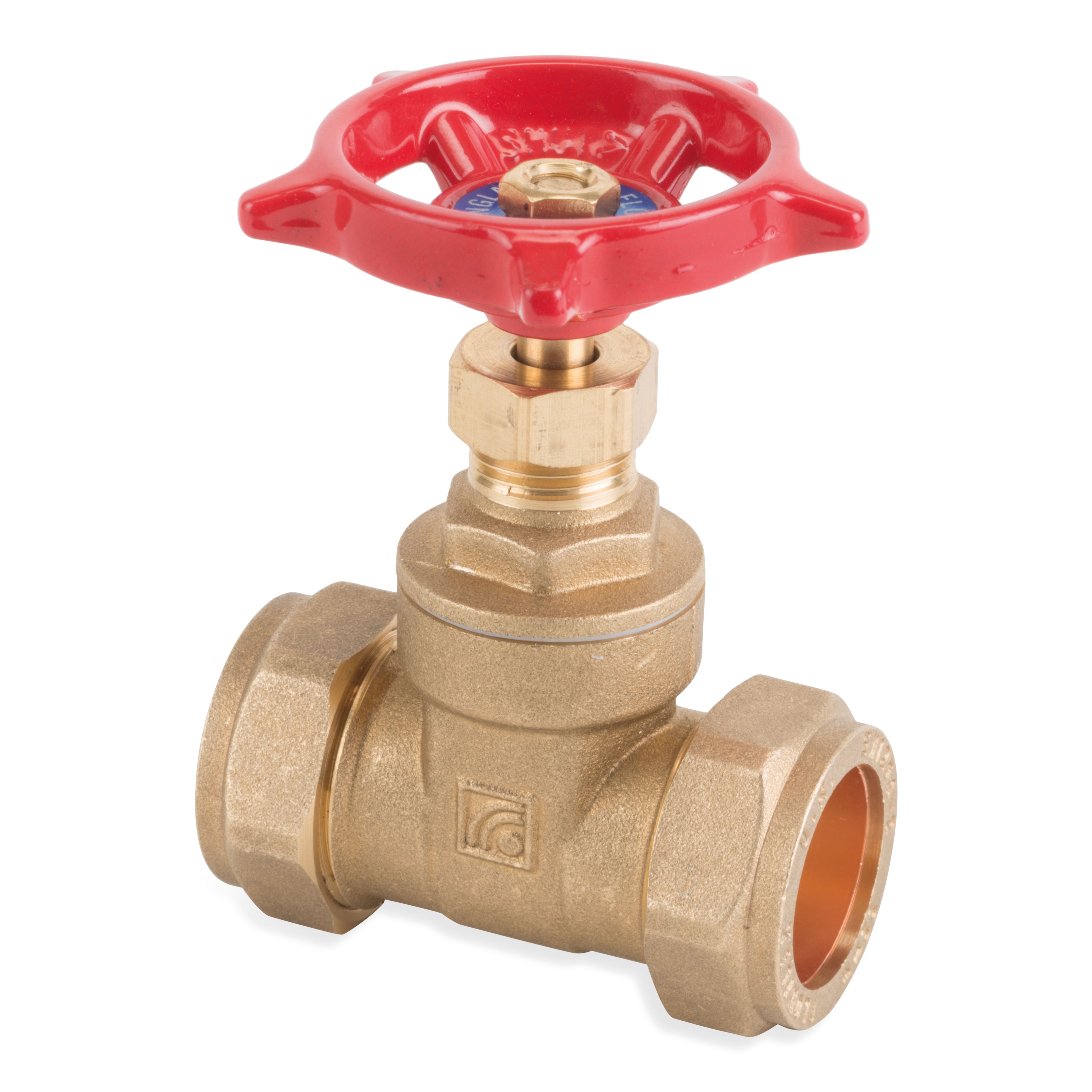
Flowflex Brass Compression Gate Valves are available in sizes 15mm to 54mm. Flowflex Brass and Bronze Female Gate Valves are available in sizes from ½” to 2”. All Flowflex Gate Valves have Aluminium Handwheels.

Applications

  • Domestic
  • Commercial
  • Industrial

Preliminaries

Unpack and check that the valve is correct for its intended usage. The valve must be compatible with the system design, pressure & temperature requirements and must also be suitable for the fluids it is intended to carry. Check that the flow paths are clear and that the threads are free from debris. To ensure ease of operation, maintenance and repair, the location of the valve should be decided during the system design phase. Valves should be appropriately supported to prevent strain on the valve and the pipework.

Equipment

Materials
  • Copper Pipe
  • Gate Valve
Tools
  • Adjustable Spanner
  • Pipe Cutting Tool
  • Internal & External Pipe Deburring Tool

Installation

Check Valve and Tube

Check Valve and Tube

Gate valves can be installed both vertically and horizontally.

Install valve in a closed position.

Female Gate Valves

Female Gate Valves

Ensure that suitable pipe supports are used close to and either side of the valve to avoid bending the valve and remove any excessive stresses. Ensure that the pipe thread is the correct length for the valve, too short risks leakage, too long risks damaging the valve. Ensure any compound or PTFE tape is used sparingly and applied to the male thread only and not on the female thread.

Do not over pack the threads, PTFE Tape is preferred.

When connecting the pipe ensure the pipe is on the correct perpendicular axis and that the threads are engaged correctly when tightening the valve. The valve should be held in position with a spanner or wrench while the connecting pipes are screwed in. Ensure the spanner or wrench is fitted to the body end, to the valve hexagon / octagon flats, adjacent to the joint.

Do not over tighten when making the connection.

Compression Gate Valves

Compression Gate Valves

Ensure that the fitting is the correct size for the pipe and that the pipe is cut to length with the ends square and clear from defects.

Unscrew the nut and olive and slide onto the pipe. Insert the pipe into the fitting ss far as the pipe stop. Slide the olive and nut back onto the fitting and tighten by hand until the pipe cannot rotate. Use spanner flats adjacent to the pipe joint being made.

Avoid over tightening.

Other Considerations

Tightening Guidance for Gate Valves with Compression Ends
Turns
Size Turns
< 28mm 1 1/4 Turns
> 28mm 3/4 Turns
Torque Settings
Size Torque
15mm 30 - 35 Nm
22mm 45 - 50 Nm
28mm 55 - 60 Nm
35mm 105 - 110 Nm
42mm 150 - 155 Nm
54mm 240 - 245 Nm
Tightening Guidance for Gate Valves with Female Threads
Torque Settings
Size Torque
1/2" 75 Nm
3/4" 100 Nm
1" 125 Nm
1 1/4" 160 Nm
1 1/2" 200 Nm
2" 250 Nm
2 1/2" 300 Nm
3" 370 Nm
4" 465 Nm

Testing

We recommend that all systems are throughly tested upon completion. Whenever possible, completed systems should also be flushed to remove debris.

Maintenance

Regular maintenance is the most efficient method of ensuring longer term uninterrupted operational efficiency. It is recommended that within the 1st year that valves should be visually inspected for leaks and that a complete manoeuvre cycle is carried out to check the valve and prevent scale from forming every 3 months. Where a valve is working under extreme conditions it is recommended to check it more frequently.

Hydraulic Installations

In hydraulic based installations, the system may be tested to 1.5 times the working pressure of the system. If higher test pressures are required, then please contact us for further advice.

Any Questions?

Our team is available for you anytime.